
In today’s rapidly evolving world of automation and electronics, controlling devices efficiently is crucial for both hobbyists and professionals. Whether you’re working on a smart home project, industrial automation, or a DIY electronics setup, understanding key components like IO controllers, PoRelay8 modules, Arduino relay wiring, and time delay switches can make a significant difference in your project’s success.
This article dives deep into these four essential topics, breaking them down into clear, actionable insights. Each section will answer a fundamental question about the component, explaining its functionality, applications, and best practices for implementation. By the end, you’ll have a solid grasp of how these devices work, how to integrate them into your projects, and why they are indispensable in modern electronics.
Let’s begin by exploring the role of an IO controller, followed by the specialized PoRelay8 module, the correct methods for Arduino relay wiring, and finally, the versatile applications of time delay switches. Whether you’re a beginner or an experienced engineer, this guide will provide valuable knowledge to enhance your projects.
What Is an IO Controller and How Does It Work?
An IO controller (Input/Output controller) serves as the critical link between a computing system and the physical world, enabling communication between microcontrollers and external devices like sensors, relays, and actuators. These versatile components play a fundamental role in automation, robotics, and electronics by managing data flow and ensuring seamless interaction between digital systems and real-world inputs and outputs.
Core Functions of an IO Controller
At its core, an IO controller performs signal conversion, translating between digital and analog formats to ensure different devices can communicate effectively. For example, it might read a variable voltage from a temperature sensor and convert it into a digital value that a microcontroller can process. Beyond conversion, the IO controller handles data routing, taking input signals from switches or sensors and directing output commands to motors, lights, or relays.
Many IO controllers also incorporate protocol management, supporting communication standards like I2C, SPI, or UART to interface with a wide range of peripherals. Some advanced models even provide electrical isolation, protecting sensitive control circuits from power surges or interference when dealing with high-voltage components.
Different Variants for Different Needs
IO controllers come in specialized forms depending on their intended use. Digital IO controllers deal with simple on/off signals, making them ideal for controlling relays or reading button presses. Analog IO controllers, on the other hand, handle variable signals, such as those from potentiometers or light sensors, allowing for precise adjustments like dimming LEDs or monitoring environmental conditions.
For larger-scale applications, networked IO controllers enable remote operation over Ethernet, Wi-Fi, or industrial protocols like Modbus. These are commonly found in smart factories and building automation systems where centralized control is necessary.
Where IO Controllers Are Used
In home automation, IO controllers regulate smart lighting, thermostats, and security systems. Industrial settings rely on them to operate machinery, monitor production lines, and enforce safety protocols. Robotics engineers use IO controllers to interpret sensor data and coordinate motor movements, while electronics hobbyists integrate them into Arduino and Raspberry Pi projects for expanded functionality.
Selecting the Right IO Controller
Choosing the best IO controller depends on several factors. The number of inputs and outputs must match the project’s requirements, ensuring there are enough ports for all connected devices. Voltage compatibility is another critical consideration—some controllers work with low-voltage circuits, while others can interface with higher-power industrial equipment.
Communication protocol support determines how easily the IO controller integrates with existing systems, with common options including I2C, SPI, and UART. For applications involving high voltages or noisy electrical environments, an isolated IO controller provides an extra layer of protection against potential damage.
The IO controller is an indispensable component in modern electronics, bridging the gap between digital systems and physical devices. Its ability to manage signals, support multiple communication methods, and protect sensitive circuits makes it invaluable across countless applications. Whether optimizing a smart home or automating industrial machinery, a well-chosen IO controller enhances efficiency, reliability, and control.
Next, we’ll examine the PoRelay8, a powerful relay module that expands automation possibilities with its unique features.
What is PoRelay8 and How Does It Enhance Automation Projects?
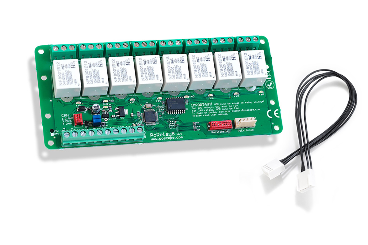
The PoRelay8 is a powerful 8-channel relay module that has become a favorite among automation enthusiasts and industrial control system designers. This compact yet robust device combines relay switching capabilities with Power over Ethernet (PoE) technology, creating a versatile solution for remote control applications. But what makes the PoRelay8 stand out from conventional relay modules, and how can it transform your automation projects?
Understanding the PoRelay8’s Core Features
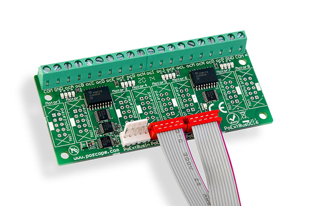
At its heart, the PoRelay8 provides eight independently controllable relay channels, each capable of switching up to 10A at 250V AC or 30V DC. What sets it apart is its integrated Power over Ethernet functionality, allowing both power and control signals to be transmitted through a single Ethernet cable. This eliminates the need for separate power supplies in distributed control systems, significantly simplifying installation and reducing wiring complexity.
The module’s built-in microcontroller handles communication protocols, supporting both Modbus TCP/IP for industrial applications and simple HTTP/HTTPS commands for web-based control. This dual-protocol approach makes the PoRelay8 adaptable to various environments, from home automation to factory floor installations. Each relay channel features optical isolation, protecting the control circuitry from electrical noise and voltage spikes that commonly occur in industrial settings.
Practical Applications of the PoRelay8
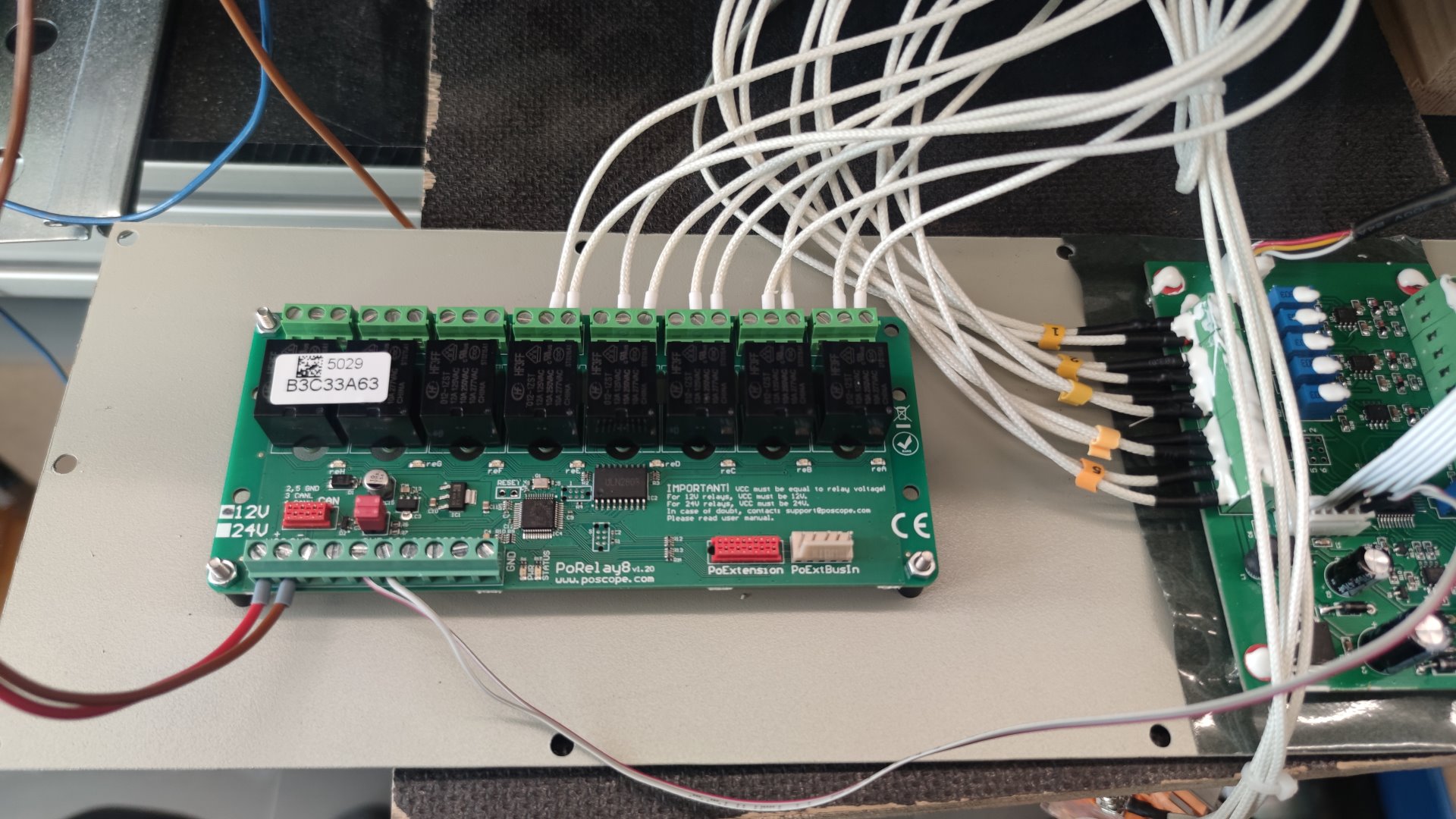
In industrial automation, the PoRelay8 excels at equipment control, enabling remote operation of motors, pumps, and conveyor systems across large facilities. Its PoE capability proves particularly valuable in these scenarios, as it allows installation in hard-to-reach locations without requiring local power outlets. Maintenance teams can monitor and control machinery from a central location, improving operational efficiency and safety.
For smart home implementations, the PoRelay8 offers professional-grade control of lighting systems, HVAC equipment, and security devices. Homeowners can integrate it with existing home automation platforms or create custom control interfaces through its web API. The module’s robust construction ensures reliable operation for critical home systems that demand uninterrupted performance.
Data center managers utilize PoRelay8 modules for power distribution unit (PDU) control, remote reboot capabilities, and equipment sequencing. The ability to power cycle servers and network equipment from a centralized management console significantly reduces downtime during troubleshooting procedures. The module’s logging features provide valuable data for analyzing power usage patterns and equipment performance.
Integration and Control Options
Connecting and programming the PoRelay8 offers multiple pathways to suit different technical skill levels. For quick setup, users can access the built-in web interface through any standard browser, configuring relay operations through an intuitive graphical interface. More advanced users can leverage the Modbus TCP protocol to integrate the module with SCADA systems or industrial PLCs.
Developers working with custom applications can communicate with the PoRelay8 using its comprehensive HTTP API, which supports JSON-formatted commands for seamless integration with modern web applications. The module’s firmware supports over-the-air updates, ensuring compatibility with future features and security enhancements without requiring physical access to the device.
Why Choose PoRelay8 Over Conventional Relays?
The PoRelay8 eliminates many limitations of traditional relay solutions by combining multiple functions into a single, network-accessible unit. Conventional relay setups typically require separate power supplies, additional communication modules, and complex wiring schemes. In contrast, the PoRelay8 delivers a plug-and-play experience with enterprise-grade reliability.
Its industrial-grade components ensure a long operational life, even in demanding environments with frequent switching cycles. The module’s compact form factor allows for high-density installations, making it ideal for control panels where space is at a premium. Advanced features like scheduled operations, conditional triggering, and event logging provide capabilities normally found in much more expensive industrial control systems.
The PoRelay8 represents a significant leap forward in relay control technology, merging robust switching capabilities with modern networking features. Its Power over Ethernet implementation, industrial-grade construction, and flexible control options make it equally suitable for professional automation projects and sophisticated DIY setups. Whether you’re automating a manufacturing process, building a smart home infrastructure, or creating a networked control system, the PoRelay8 delivers performance, reliability, and convenience in a single package.
Next, we’ll examine proper Arduino relay wiring techniques to ensure safe and effective integration of relays in microcontroller projects.
How to Properly Wire Relays with Arduino for Safe and Effective Control
Relays serve as essential bridges between low-power Arduino circuits and high-voltage devices, but improper Arduino relay wiring can lead to equipment damage or safety hazards. Whether you’re controlling lights, motors, or appliances, understanding correct wiring techniques ensures reliable operation while protecting your Arduino board. Let’s examine the crucial steps and considerations for proper Arduino relay wiring.
Understanding Relay Fundamentals in Arduino Projects
A relay functions as an electrically operated switch, allowing your Arduino’s 5V or 3.3V outputs to control devices requiring much higher voltages. The typical relay module contains three critical connection points: the control side (connected to Arduino), the switched side (for your high-power device), and the power supply for the relay coil. Most Arduino-compatible relay modules include optocouplers for electrical isolation, protecting your microcontroller from voltage spikes.
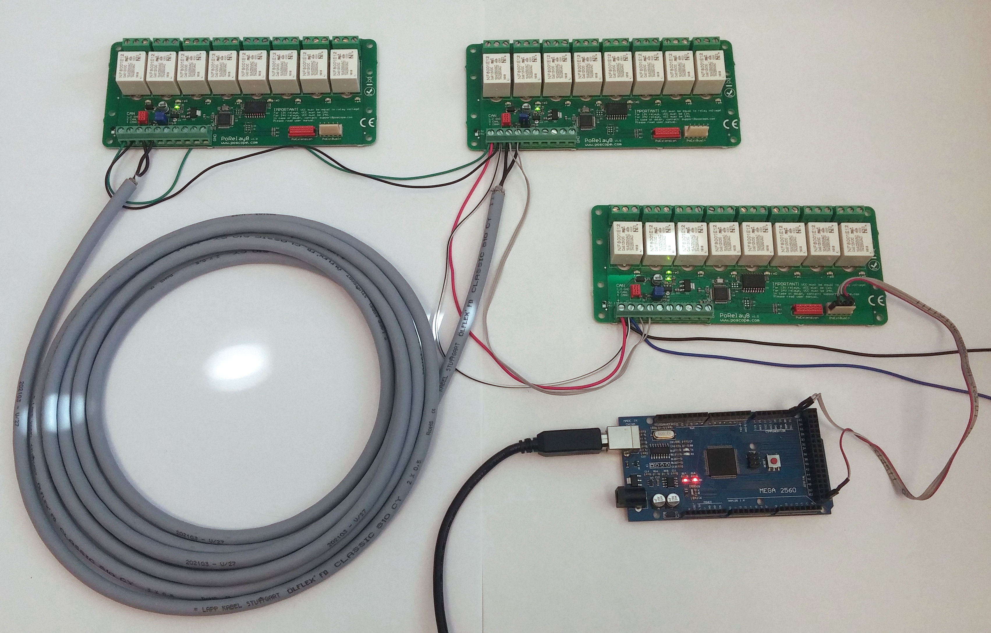
When examining Arduino relay wiring, you’ll encounter two common module types: single-channel boards ideal for simple projects, and multi-channel versions (like 4 or 8 relay boards) for complex automation. These modules typically operate with 5V or 12V coil voltages, so verify your specific relay’s requirements before connecting power. The switching contacts usually handle 10A at 250V AC or 30V DC, sufficient for most household appliances and industrial control applications.
Step-by-Step Wiring Implementation
Begin your Arduino relay wiring by connecting the control side: attach the module’s VCC pin to Arduino’s 5V output, GND to Arduino’s ground, and the IN pin to a digital output pin. For multi-relay boards, each relay will have its own control pin. Use appropriately sized jumper wires, keeping high-voltage wiring completely separate from these low-voltage control connections.
For the load side connections, treat the relay like a mechanical switch in your high-voltage circuit. Connect the live wire from your power source to the relay’s common (COM) terminal, then run a wire from the normally open (NO) terminal to your device. The neutral wire should connect directly to your device, bypassing the relay entirely. Always double-check that all high-voltage connections are secure and properly insulated before applying power.
Critical Safety Considerations
Proper Arduino relay wiring demands strict attention to safety when dealing with mains voltage. Always work with the power disconnected when making or modifying connections. Use appropriate wire gauges for your current requirements – typically 18 AWG for most household currents. Implement strain relief on all connections to prevent wires from pulling loose over time.
For additional protection, consider these enhancements to your Arduino relay wiring: install a fuse in series with your high-voltage circuit, use cable glands for strain relief where wires enter enclosures, and maintain proper separation between low and high-voltage wiring. In damp or dusty environments, apply silicone conformal coating to the relay module’s circuit board to prevent corrosion and short circuits.
Programming and Troubleshooting Techniques
After completing your Arduino relay wiring, test the system with a simple sketch that toggles the relay on and off. Start with low-voltage devices before progressing to mains-powered equipment. Common issues include relays not activating (check coil power and control signal), chattering (add a small delay in code), or unexpected behavior (verify your wiring against the relay module’s datasheet).
For more reliable operation, implement these programming best practices: include a brief delay (10-50ms) between relay state changes to reduce contact wear, use a flyback diode across the relay coil if your module doesn’t include one, and consider implementing software debouncing for applications where switch bounce might cause problems. Monitor your relay’s operational temperature during extended use – excessive heat may indicate an overloaded contact.
Advanced Wiring Configurations
Once comfortable with basic Arduino relay wiring, explore more sophisticated setups. For high-current applications, consider using your Arduino-controlled relay to trigger a contactor that handles the main load. In safety-critical systems, implement redundant relays in series for fail-safe operation. For three-phase motor control, use multiple relays configured in proper interlock patterns.
Wireless control options expand your possibilities – pair your Arduino relay wiring with Bluetooth or WiFi modules for remote operation. For industrial applications, integrate your relay module with PLCs using appropriate interface circuits. Always document your wiring thoroughly, including wire colors, connection points, and circuit protection details for future maintenance and troubleshooting.
Optimizing Relay Performance and Longevity
Proper Arduino relay wiring extends beyond initial connection – implement these practices for maximum reliability: periodically inspect connections for corrosion or loosening, clean relay contacts with appropriate solvents if arcing occurs, and replace relays showing signs of contact degradation. Consider contact wetting current for low-power applications to ensure proper switching.
For noise-sensitive environments, add RF suppression capacitors across relay contacts. In applications with inductive loads (motors, solenoids), incorporate snubber circuits to protect contacts from voltage spikes. Monitor your relay’s operational cycle count – most quality relays are rated for 50,000 to 100,000 operations, after which contact resistance may increase significantly.
By mastering these Arduino relay wiring techniques and best practices, you’ll create robust control systems that safely interface your Arduino projects with high-power devices. The proper implementation ensures not only immediate functionality but also long-term reliability across various applications.
How Do Time Delay Switches Work and Where Are They Used?
Time delay switches introduce precise temporal control into electrical circuits, allowing users to automate operations based on predetermined intervals. These clever devices bridge the gap between simple on/off control and sophisticated automation systems. But what exactly makes time delay switch mechanisms so valuable across residential, commercial, and industrial applications?
The Mechanics Behind Time Delay Operation
A time delay switch functions by interrupting or initiating power flow after a preset duration, using either mechanical or electronic timing mechanisms. Mechanical versions typically employ thermal or pneumatic delay systems where a heating element or air piston creates the time lag. Modern electronic time delay switches utilize digital circuits with crystal oscillators or RC (resistor-capacitor) networks for more precise timing control, often adjustable from milliseconds to several hours.
These devices generally feature three operational modes: delay-on-make (starts timing when powered and closes contacts after delay), delay-on-break (maintains circuit during delay period after power removal), and interval timing (creates precise pulses). Advanced models incorporate multiple timing ranges, adjustable via dip switches or digital interfaces, while industrial-grade versions offer programmable logic for complex sequencing applications.
Practical Applications Across Industries
In residential settings, time delay switches prevent bathroom exhaust fan overuse by automatically shutting off after 15-60 minutes of operation. They similarly control attic fans, whole-house ventilation systems, and heat lamp circuits. Home security systems employ these switches to maintain lighting after motion detection, creating the illusion of occupancy during vacations.
Commercial buildings utilize time delay switch technology in escalator power management (staggered startup reduces peak demand), restroom lighting control (auto-off for energy savings), and commercial kitchen hood systems (continued ventilation after cooking ceases). Theatrical lighting systems rely on precision timing switches for sequenced scene transitions and special effects timing.
Industrial applications demonstrate the time delay switch‘s robustness in motor control centers (preventing simultaneous startup of multiple motors), conveyor belt synchronization, and pump alternation systems. Manufacturing processes use them for precise dwell times in automated assembly lines, while wastewater treatment plants apply them for sequenced aeration cycles in biological reactors.
Installation Considerations and Best Practices
Proper time delay switch installation requires understanding both electrical requirements and operational parameters. Always verify voltage compatibility (120VAC, 240VAC, or low-voltage DC models) and current ratings before installation. Consider environmental factors – industrial models feature robust enclosures for dusty or humid conditions, while explosion-proof versions exist for hazardous locations.
For optimal performance, install time delay switch units in accessible locations with adequate ventilation, away from heat sources that might affect timing accuracy. When used with inductive loads (motors, transformers), add appropriate contact protection such as snubber circuits. Label switches clearly with their function and timing parameters for easy identification during maintenance.
Troubleshooting Common Time Delay Issues
When a time delay switch malfunctions, symptoms typically include failure to trigger, inaccurate timing, or contact welding. Begin diagnostics by verifying power supply integrity and load compatibility. For mechanical timers, check for worn gears or sticking mechanisms; electronic versions may suffer from capacitor degradation or oscillator circuit failures.
Inconsistent timing often stems from voltage fluctuations – consider adding voltage regulation for sensitive applications. Contact failures frequently result from excessive inrush currents – verify your switch’s make/break capacity matches the connected load. Many modern electronic time delay switch units include LED status indicators and fault codes to simplify diagnostics.
Innovations in Time Delay Technology
Recent advancements in time delay switch design incorporate IoT connectivity for remote monitoring and adjustment via smartphone apps. Solid-state versions eliminate moving parts entirely, using thyristors or MOSFETs for silent operation and extended lifespan. Some cutting-edge models now integrate with building automation systems through BACnet or Modbus protocols.
Energy harvesting time delay switches now operate without external power sources, using kinetic energy from button presses or thermal differentials. Programmable logic timers allow complex multi-step sequences in a single device, while safety-rated versions provide failsafe operation for critical processes. These innovations continue expanding application possibilities across all sectors.
Selecting the Right Time Delay Solution
Choosing an appropriate time delay switch requires analyzing several factors: required timing range (seconds, minutes, or hours), switching accuracy (±1% for precision processes vs ±10% for general use), load characteristics (resistive, inductive, or capacitive), and environmental conditions. Consider whether you need fixed or adjustable timing, and whether visual status indicators would benefit operation.
For basic applications, simple mechanical timers offer reliability at low cost. Complex automation projects may justify microprocessor-controlled models with multiple timing channels and communication capabilities. Always verify third-party certifications (UL, CE, ATEX for hazardous areas) to ensure compliance with local regulations and safety standards.
The Future of Time-Controlled Switching
As smart buildings and Industry 4.0 concepts evolve, time delay switch technology increasingly integrates with predictive systems using machine learning algorithms. Next-generation devices will automatically adjust timing parameters based on usage patterns and environmental sensors. Wireless power transfer may eliminate wiring constraints entirely, while self-diagnosing switches will predict maintenance needs before failures occur.
These advancements promise to make time delay switch components even more versatile and intelligent, transforming them from simple timing devices into integral parts of adaptive control systems. Whether for energy conservation, process optimization, or safety enhancement, time-controlled switching will continue playing a vital role in electrical system design across all sectors.
Harnessing the Power of Control Components
From the versatile IO controller that bridges digital and physical worlds to the network-enabled PoRelay8 that revolutionizes remote switching, we’ve explored how modern control components transform automation capabilities. The proper Arduino relay wiring techniques ensure safe interaction between microcontrollers and high-power devices, while time delay switches introduce precision timing that optimizes everything from industrial processes to home automation.
These four components – the IO controller, PoRelay8, proper Arduino relay wiring, and time delay switch – represent fundamental building blocks in today’s control systems. Each serves a unique purpose: the IO controller manages signal conversion and data flow, the PoRelay8 delivers networked relay control, correct Arduino relay wiring enables safe high-power switching, and the time delay switch adds crucial temporal dimension to automation.
As technology advances, we’re seeing these components become more integrated, intelligent, and interconnected. The IO controller now often includes built-in timing functions, while modern time delay switches incorporate relay outputs and networking capabilities. The PoRelay8 exemplifies this convergence, combining relay control with Power over Ethernet in a single package. Even basic Arduino relay wiring has evolved with the introduction of smarter, self-protecting relay modules.
For engineers, hobbyists, and system integrators, mastering these components means unlocking new possibilities in automation design. Whether creating a simple timed lighting system or programming complex industrial sequences, understanding how to implement IO controllers, PoRelay8 modules, proper Arduino relay wiring, and time delay switches provides the foundation for reliable, efficient control systems.
The future promises even greater integration, with AI-enhanced IO controllers, self-configuring PoRelay8 systems, wireless Arduino relay wiring alternatives, and adaptive time delay switches that learn from usage patterns. As these technologies evolve, their core principles remain essential knowledge for anyone working in electronics and automation.
By combining these components creatively – perhaps using an IO controller to manage sensors that trigger a PoRelay8 through properly implemented Arduino relay wiring, all coordinated by precision time delay switches – you can build systems that are more than the sum of their parts. This synergy between components is what makes modern automation so powerful and versatile.
As you embark on your next project, remember that successful implementations begin with understanding these fundamental elements. Whether you’re automating your home, prototyping an industrial control system, or developing the next generation of smart devices, the principles behind IO controllers, PoRelay8 modules, Arduino relay wiring, and time delay switches will continue to serve as vital tools in your technical arsenal.